
Structural ceramics, such as alumina, zirconia, magnesia, silicon carbide, and silicon nitride exhibit excellent mechanical and physical properties. These ceramics have been successfully used in the area where high hardness, superior wear resistance, low thermal and electrical conductivity, chemical stability, and high thermal resistance properties are desirable. Also, the retention of these properties at elevated temperatures provides an exclusive solution for several industrial applications: electronic, automotive, aviation, medical and so on. However, despite having these superior properties, structural ceramics are hindered from several applications due to their low fracture toughness (~3-5 MPa-m½) and high hardness (~1200-2200 Knoop hardness). In addition, unacceptable tool wear, insufficient accuracy, mechanical or thermal damage of the work piece are the main limiting factors that prevent the manufacturing of accurate geometries in ceramic components using conventional machining techniques. Furthermore, achieving a higher material removal rate along with a good surface finish continue to remain as critical issues associated with these ceramics. In this case, laser machining appeared as an innovative and potential tool for bulk material removal and efficient and rapid fabrication technique for complex structures of ceramics.
Laser-material interaction:
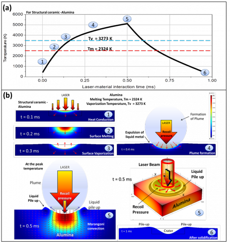
During laser machining, when a high energy laser beam (~106 J/m2) strikes on the material surface, the surface undergoes sudden temperature rise (heating: absorption of the laser energy) and fall (cooling: self-quenching by bulk material; and heat losses due to radiation and convective cooling) that in turn causes the several physical phenomena, such as heating, melting, vaporization, and plume formation (Figure 1). With the sufficient laser energy density (~106 J/m2) and laser-material interaction time, the surface experiences the localized surface melting and vaporization. Surface evaporation involved with the emission of neutral atoms or molecules of the material into the gas that shield the laser–material interaction zone. The vapor particles evaporated from the melt pool is significantly cooler and denser than the vapor-surrounding laser–material interaction zone that in turn condense back to the surface causing a recoil pressure on the liquid melt pool underneath. For the higher intensity laser beams (≥ 106 J/m2) and shorter pulse duration (0.1 to 10 ms), the magnitude of resulting recoil pressure is very high and induce the shock waves sufficient enough to generate a hydrodynamic melt motion in the liquid melt pool 3. As a consequence, the liquid metal ejected out from the crater and creates a liquid pile-up or crown. At the end of the laser–material interaction (or end of laser pulse), the liquid material tends to return to its place due to the gravitational force. However, due to self-quenching effects and higher cooling rates (∼105 K/s) the liquid material solidifies instantaneously and the tangential stress, exerted due to the surface tension of the material gives shape to the solidified material. As a result, a significant amount of material is removed and typical surface topography is generated during laser machining (Figure 1).
Classification of laser machining based on beam movement:
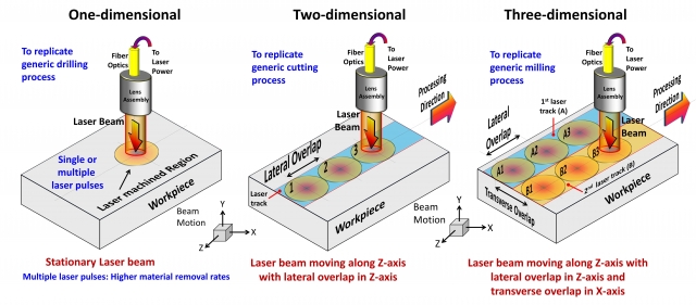
In past, considerable amount of experimental and computational works have been published to improve the quality of laser machining by employing various types of lasers: CO2, excimer, and Nd:YAG. These lasers can be operated either by continuous wave (CW), or pulse mode (PM), (mili-, nano, pico- and femto-second lasers). In CW, the output energy of the laser beam is constantly ON for a specific amount of time; whereas in PM, the lasers concentrate their output energy into shorter time high-power bursts. The PM lasers can either fire single pulse or a series of pulses (multiple) at regular intervals. In both cases, the instantaneous power densities can be extremely high (~107 J/m2), and as a result, a larger volume of material is removed. However, most of these studies show that the higher material removal rate can be achieved by using PM lasers (with applying multiple laser pulses) and considered as a preferable machining technique for structural ceramics. PM laser machining can be classified as one-, two-, or three-dimensional machining to replicate generic drilling, cutting, and milling processes, respectively (Figure 2).
One-dimensional laser machining can be carried out by either a single laser pulse or multiple laser pulses. While, two- and three-dimensional laser machining only be carried out by using moving laser beam with applying multiple laser pulses in a repeated manner. Because of this distinct variation in pulse delivery (single or multiple), laser beam movement (scanning speed), and in lateral overlap (distance between two laser pulses or Dist or OL) and/or transverse overlap (distance between two laser tracks or OT) can dramatically vary the evolving surface topography on the machined surface. This is truly a footprint of selected laser machining parameters such as scanning speed of laser beam (Vin), application of laser pulses at predefined pule rates (f), lateral overlap or distance between two laser pulses, and transverse overlap or distance between two laser tracks. Although, the nature of surface topography may vary, principally the various physical phenomena behind formation of the surface topography remain same for 1-, 2-, or 3D laser machining. Hence, the prime objective of the present study is to systematically understand the mechanism of evolution of surface topography during the impact of a single laser pulse under one-dimensional machining. Subsequently, this understanding will be extended to predict the surface topography during multi-dimensional laser machining processes.
An integrated computational and experimental approach:
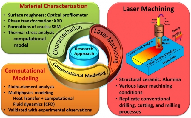
In the laser machining process, all the physical phenomena (or dynamics) happened in small confined volume (~10-10 m3) for very short time duration (< 10-3 s). Furthermore, due to the localized nature of laser beam the surface reaches to the extremely high temperature (> 5000 K) with in very short time (< 0.5 ´ 10-3 s). In addition, the in-situ measurement of the thermo-physical properties in these severe conditions such as high temperature, short time duration, and small interaction volume is an extremely difficult task. In consequence, it is extremely challenging to investigate the evolution of surface topography through experimental analyses. Hence, computational modeling approach (via finite element method-FEM/FEA) can be considered as an effective solution. In light of this, an integrated computational and experimental approach was employed in the present efforts to investigate the evolution of surface topography/ profile/ roughness or physical texture during laser machining of structural ceramic alumina (Al2O3). The integrated computational and experimental approach overcomes the difficulties associated with the in-situ measurements of thermo-physical properties, which can provide more insight to understand the laser-material interaction and its consequent effects on the evolving surface topography /profile/ roughness/ physical texture (Figure 3). The computational model was designed, developed, and validated with the experimental observation for better accuracy.
Multi-step Computational Model:
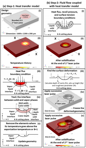
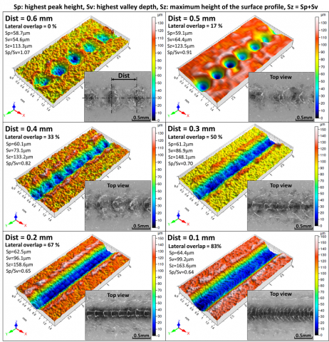
The laser machining involves change in phases and associated effects on the surface topography. During heating, as the temperature increases, material changes its phase from solid to liquid and liquid to vapor phase. The portion of material that attains the temperature above vaporization temperature is consequently removed due to evaporation. Similarly, molten material changes its phase from liquid to solid during cooling cycle. Therefore, the multi-step computation model was purposely designed and developed to simulate the phase change effects and predict the instantaneous surface deformation. In the present efforts, the integrated computational approach involving various physical phenomena for predicting surface profile during pulse mode (PM) laser machining of alumina is schematically presented in Figure 4. To validate the predictions of this computational model, the optical profilometer was used to measure the surface roughness parameters (Sp, Sv, and Sz) for various distances between two pulses (Dist = 0.1 to 0.6mm), as shown in Figure 5. The deviation between predicted and experimentally measured surface roughness parameters are within the range of ± 3.5%, thereby successfully validating the computational model.
Related Publications by the Group
- “Theoretical Evaluation of Thermal Stresses during Laser Machining of Structural Alumina.” Hitesh D. Vora, Narendra B. Dahotre, Submitted in Journal of European Ceramic Society, (May 2014).
- “Evolution of Surface Topography during Three-Dimensional Laser Machining of Structural Alumina: Integrated Experimental and Computational Approach.” Hitesh D. Vora, Narendra B. Dahotre, Submitted in Ceramics International, (May 2014).
- “Laser Machining of Structural Alumina: Influence of Moving Laser Beam on the Evolution of Surface Topography.” Hitesh D. Vora, Narendra B. Dahotre, International Journal of Applied Ceramic Technology, 2014, 1-14.
- "One-Dimensional Multipulse Laser Machining of Structural Alumina: Evolution of Surface Topography." Hitesh D. Vora, S. Santhanakrishnana, S.P. Harimkar, Sandra K.S. Boetcher, Narendra B. Dahotre, International Journal of Advanced Manufacturing Technology 2013, 68(1), 69-83.
- “Computational Modeling and Experimental Based Parametric Study of Multi-Track Laser Processing of Alumina”, Marco A. Moncayo, Soundarapandian Santhanakrishnan, Hitesh D. Vora, Sameer R. Paital, and Narendra B. Dahotre, Optics and Laser Technology, Vol. 48, pp. 570-579, 2013.
- “Laser Surface Modification of Alumina: Integrated Computational and Experimental Analysis”, Marco A. Moncayo, Soundarapandian Santhanakrishnan, Hitesh D. Vora, Sameer R. Paital, and Narendra B. Dahotre, Ceramic International, Vol. 39, pp. 6207-6213, 2013.
- "Evolution of Surface Topography in One-Dimensional Laser Machining of Structural Alumina." Hitesh D. Vora, S. Santhanakrishnana, S.P. Harimkar, Sandra K.S. Boetcher, Narendra B. Dahotre, Journal of European Ceramic Society 2012, 32 (16), 4205–4218.
- "Laser Machining of Structural Ceramics" Hitesh D. Vora, Narendra B. Dahotre, The Bulletin of the American Ceramic Society. June‐July (2013), 92(5), 29‐30.
- 'Laser Machining of Structural Ceramics: An Integrated Experimental and Numerical Approach for Surface Finish,' Hitesh Vora, PhD Dissertation, UNT Digital Library, 2013.
- “Computational Predictions in Single Dimensional Laser Machining of Alumina.” Samant, A.N., and Dahotre, N.B., Int. J. Mach. Tools Manuf ., 2008, 48, 1345-1353.
- “Ab Initio Physical Analysis of Single Dimensional Laser Machining of Silicon Nitride.” Samant, A.N., and Dahotre, N.B., Adv. Eng. Mater., 2008, 10, 978-981.
- “An integrated computational approach to single dimensional laser machining of magnesia.” Samant, A.N., and Dahotre, N.B.,Opt. Lasers Eng., 2009, 47, 570-577.
- “Differences in Physical Phenomena Governing Laser Machining of Structural Ceramics.” Samant, A.N., and Dahotre, N.B., Ceram. Int., 2009, 35, 2093-2097.
- “Laser Machining of Structural Ceramics- A Review.” Samant, A.N., and Dahotre, N.B., J. Eur. Ceram. Soc. 2009, 29, 969-993.
- , “Computational Approach to Photonic Drilling of Silicon Carbide.” Samant, A.N., Daniel, C., Chand, R.H., Blue, C.A., and Dahotre, N.B.Int. J. Adv. Manuf. Technol., in press, DOI: 10.1007/s00170-009-2004-0.
- “Physical Effects of Multipass Two Dimensional Laser Machining of Structural Ceramics.” Samant, A.N., and Dahotre, N.B., Adv. Eng. Mater., 2009, 11(7), 579-585.
- “Absorptivity Transition in 1.06 μm Wavelength Laser Machining of Structural Ceramics.” Samant, A.N., and Dahotre, N.B., Int. J. Appl. Ceram. Technol., in press.
- “In-situ Surface Absorptivity Prediction During 1.06 μm Wavelength Low Aspect Ratio Machining of Structural Ceramics.” Samant, A.N., Du, B., and Dahotre, N.B., Phys. Status Solidi., 2009, 206(7), 1433-1439.
- “Three-dimensional Laser Machining of Structural Ceramics.” Samant, A.N., and Dahotre, N.B., J. Manuf. Processes, 2010, 12(1), 1-7.